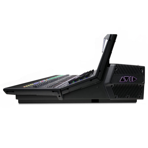
AVID 9900-71211-00 CKM Channel Knob Module
Each Channel Knob Module is capable of providing channel parameter control with the use of 32 dual-function encoders that provide switch and rotary functions.
Each CKM is associated to the bank of eight faders below it, and the Channel Touch Module above it (if present). The CKM is operating in one of the following modes: Channel Strip mode or Channel Control mode.
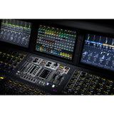
1 – Encoder Display
The encoder display is showing the parameter that is currently spilled to the encoder and the actual value of the parameter (such as dB level for gain or frequency of an EQ frequency band). The display also is showing a “virtual” encoder, which is showing the position of the encoder relative to the parameter value. For gain parameters, the virtual encoder surround fills in to indicate level. For bus assign parameters, the encoder surround fills in completely when the corresponding channel is assigned, and is empty (black) when the channel is unassigned.
2 – Sel
Sel is assigning a secondary parameter to the corresponding encoder, or toggling a secondary function of the current parameter, where available.
3 – In
In toggles an individual parameter on/off, where available. For example, during the time EQ is assigned to the CKM, pressing the In switch for the knob controlling Lo band gain toggles that filter in/out. The switch lights by the time the parameter is enabled (in).
4 – Encoder
Rotating the encoder is adjusting the currently assigned parameter, as shown in the encoder display. For certain parameters, pressing the encoder is toggling the parameter on/off (such as the Hi Gain parameter when EQ is assigned). Encoders are color-coded by function. See Encoder Color Coding for more information.
5 – Channel Control Function Switch
The Channel Control Function switch is assigning a group of parameters for the currently selected channel to the 32 encoders on the CKM. See Channel Control Functions for more information.
6 – Parameter Bank Switches
The Left and Right Parameter Bank switches are giving you the capability to assign the next or previous page of parameters to the encoders, and are available in both Channel Strip and Channel Control modes. A switch lights when there is a previous or next page of parameters to access.
 USD
USD EUR
EUR
 AUD
AUD
 GBP
GBP
 JPY
JPY